-
×
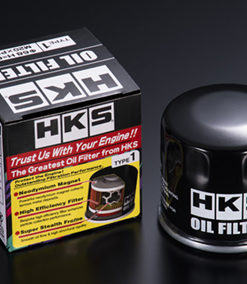 HKS Hybrid Sports Ölfilter Type 1 φ68mm X H65 M20x1.5
Lieferzeit: 3-4 Werktage
1 × 25,90 € -
×
 RAYS Volk Racing Center Cap Flat Small O-Ring BR No. 60
Lieferzeit: 2-3 Wochen Expresslieferung Japan
1 × 47,90 € -
×
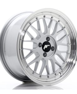 Japan Racing JR23 17 Zoll 8J ET35 4x100 Hyper Silver w/Machined Lip
Lieferzeit: 1-2 Wochen
1 × 215,00 € -
×
 Japan Racing JR26 16 Zoll 8J ET25 4x100/108 Silver Machined Face
Lieferzeit: 1-2 Wochen
1 × 170,00 € -
×
 Japan Racing JR26 16 Zoll 8J ET25 4x100/108 Gold w/Machined Lip
Lieferzeit: 1-2 Wochen
1 × 170,00 €
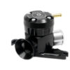
Atomic Boost Controller Single Stage [GFB]
82,00 €
inkl. 20 % MwSt. zzgl. Versandspesen
Lieferzeit: 1-2 Wochen
Artikelnummer: 218002
Kategorien: Performance, Elektronik, Boost Controller
Schlagwort: GFB
Brands: GFB
Marke: GFB
Atomic Manual Boost Controller
• Most reliable and cost effective boost control device on the market
• More stable boost curve than “ball-andspring” types
• Simple installation, works on almost any turbo-charged engine, petrol or diesel, internal or external wastegate
• Set-and-forget
• Can be used in conjunction with factory boost control system, or stand-alone
How does a boost controller work ?
There are 2 main components of a boost control system on a turbocharged engine: the wastegate with actuator and the boost controller. Note that some turbo cars do not use a boost controller as such, instead they rely on the spring rate in the wastegate actuator to achieve the desired boost level.
There are two types of wastegates; internal and external. Internal wastegates are found on the vast majority of turbo cars, where a flap-type valve is built into the turbocharger exhaust housing, and is opened by a remote diaphragm actuator. The external type usually use a poppet-style valve attached directly to the diaphragm actuator as one unit, which is plumbed into the exhaust header before the turbo, and dumps back into the exhaust after the turbo.
Both types of wastegate open a path for exhaust gas to bypass the turbo, thereby limiting the amount of gas available for making boost. The diaphragm actuators in both cases are controlled by the boost pressure itself, which creates a feedback loop boost control system; as the boost pressure increases, it pushes the diaphragm actuator (and therefore the wastegate valve) further open, which results in the boost stabilizing at a set level determined by the spring rate in the actuator.
A boost control device is commonly used in modern turbo engines which alters the boost signal that reaches the wastegate actuator. If the actuator sees a lower boost signal than is actually present, the wastegate will open less. This results in greater exhaust gas flow through the turbo, which increases boost. For example, if the actuator spring is set to 7 psi (i.e. when the valve is fully open, boost level is 7 psi) but the boost control device only allows 5 psi to reach the actuator, it will open the wastegate valve less, so more exhaust flows through the turbo, spinning it more quickly, so that the actual boost produced will be greater than 7 psi; say, 10 psi.
The boost control device is designed to reduce the pressure reaching the actuator, which it does by ‘bleeding off‘ a specific amount of air from the supply hose. This can be done electronically through the ECU by pulsing a solenoid-type valve in the supply hose, or mechanically by placing a ‘controlled leak‘ in the supply hose.
GFB boost controllers are the latter type, which may not sound incredibly scientific, but there are a few design criteria that are critical to performance. Essentially, a GFB boost controller receives boost pressure from the turbo compressor, passes it through a restrictor (which is necessary, or the turbo would simply fill the supply hose as fast as the controller could bleed it off), where a measured amount of air is bled out of the hose that leads to the wastegate actuator. Note that it is not possible to reduce the boost level below the setting of the actuator spring, only increase it. It is however possible to reduce boost below standard on cars that originally had ECU/solenoid controlled boost.
Do GFB boost controllers use a ball and spring?
No. Some manufacturers use a ‘ball and spring’ arrangement in their manual boost controllers, with the claim that it brings the boost on faster by keeping the wastegate closed until the boost has nearly reached it’s peak level. This is a sound idea in theory, however it is worth noting that the „gated“ ball-and-spring system offered by other manufacturers is incapable of holding back more than a paltry 2psi – certainly not enough to live up to the advertising claims.
Another nail in the coffin for the ball-and-srping design is poor boost stability. Since it is a dynamic system, and the ball can move slightly differently each time your engine comes on boost, the size and flow properties of the flow path through the restrictor and around the ball can change each time. This can lead to poor boost stability and random variations in peak boost level. The ball can even flap around like a pea in a referee’s whistle whilst air is flowing through, resulting in a fluctuating output signal from the controller. Grab a boost gauge, a compressed air supply and a pressure regulator and see for yourself.
GFB boost controllers use a more consistent needle-valve bleed system, which brings brings boost on just as fast as any ball-and-spring system, and generally more quickly than a factory boost control system.
How much extra boost can I run when using a GFB boost controller?
It is very important to be sensible when raising the boost limit on turbocharged cars. Power is directly related to the amount of air and fuel that makes it to the engine cylinders, but lifting the boost level is only one way of doing this. While in most cases it is quite safe to increase the boost by about 10-20%, keep in mind that every component in an engine comes from the factory designed to operate most efficiently at the level it leaves the factory at. If you intend to raise the boost to any more than 20% above factory, you will need to check things like fuel delivery, the intercooler, ignition timing, etc to ensure that they are capable of supporting the increase in power. It is also important to realise the mechanical limits of components, a good example being the ceramic turbine wheels in the turbos found in Skylines, which will take no more than about 14psi without losing blades.
A GFB boost controller will give you the added benefit of not only being able to adjust the peak boost level, but in most cases will bring the boost on earlier, resulting in more power throughout the rev range.
To get the most out of the extra boost it is best to ensure that the engine can breathe properly. A good exhaust is the first place to start. Then follow the inlet tract all the way to the engine, looking for restrictions in the form of resonators, sharp bends or reductions in diameter. Manufacturers will often purposely build in such restrictions to muffle intake noise or prevent overboosting. Removing airflow restrictions means the turbo doesn’t have to work as hard to get the boost to the engine.
Why does the boost in my car tend to taper off with increased boost at high RPM?
This is a sign that your turbo system is nearing the limit of its efficiency. Most factory turbos have small turbine housings to reduce lag, but the problem is at high RPM it can cause a large enough restriction to push the wastegate open as the revs increase, often referred to as wastegate creep.
This can also be caused by restrictions in the factory turbo compressor inlet and outlet pipes that also contribute to tapering boost levels, such as convoluted hose sections. The boost controller usually gets its boost signal from directly after the turbo, so the boost at this point is often likely to hold steady. However, restrictions further downstream (corrugated pipes, small intercooler, sharp bends or reductions in diameter) will cause a pressure drop at elevated RPM, particularly if the car is modified and making more power than factory.
It is also important to realise that in stock or mildly modified engines it is probably much safer to drop the boost level a little towards redline. The inertial loads on the reciprocating components increase exponentially with RPM, which is why you will often see the factory ECU drop a few psi near redline. Generally this will occur on cars with small factory turbos, and it is probably in the best interests of the health of the turbo for this to happen unless your engine is built to handle it.
| fahrzeugmarke | |
|---|---|
| Hersteller | |
| Gewicht | 1 |
Nur angemeldete Kunden, die dieses Produkt gekauft haben, dürfen eine Rezension abgeben.
Ähnliche Produkte
+
Dieses Produkt weist mehrere Varianten auf. Die Optionen können auf der Produktseite gewählt werden
Schnellansicht
856,80 €
inkl. MwSt.
Lieferzeit: 1-2 Wochen
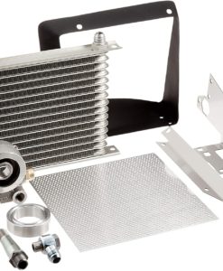
Brands: Mishimoto
+
Dieses Produkt weist mehrere Varianten auf. Die Optionen können auf der Produktseite gewählt werden
Schnellansicht
2.982,95 € – 3.557,00 €
inkl. MwSt.
Lieferzeit: 2 Wochen
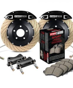
Brands: Stoptech
Angebot!
inkl. 20 % MwSt.
Lieferzeit: 1 Woche
Brands: EBC
+
Dieses Produkt weist mehrere Varianten auf. Die Optionen können auf der Produktseite gewählt werden
Schnellansicht
162,60 €
inkl. MwSt.
Lieferzeit: 1-2 Wochen
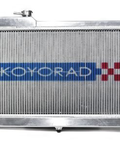
Brands: Mishimoto
Performance
Milltek HJS Tuning ECE Downpipe für Hyundai i30N 2017/2018 (Performance) non-OPF Models only
2.100,00 €
inkl. 20 % MwSt.
Lieferzeit: 1-2 Wochen
Brands: Milltek Sport

![Atomic Boost Controller Single Stage [GFB]](https://jv-imports.at/wp-content/uploads/cm//2/1/218002.jpg)




Rezensionen
Es gibt noch keine Rezensionen.